

High-speed retroreflex point ellipsometer for imaging and measuring rapid material changes
In many areas of material processing, it is crucial to characterize the condition before, during, and after treatment. Sensors that can also visualize these changes are ideal. Furthermore, the user desires minimal setup and adjustment effort, while the automation engineer needs a signal if the material properties change significantly.
Using the application example of a LIDT test system that characterizes the damage threhold of optical components against laser radiation, it was shown in cooperation with the Fraunhofer Institute IOSB that imaging retroreflex point ellipsometers can very well meet these requirements and wishes.
Application example: Detector of a LIDT testing system
Optics in the test
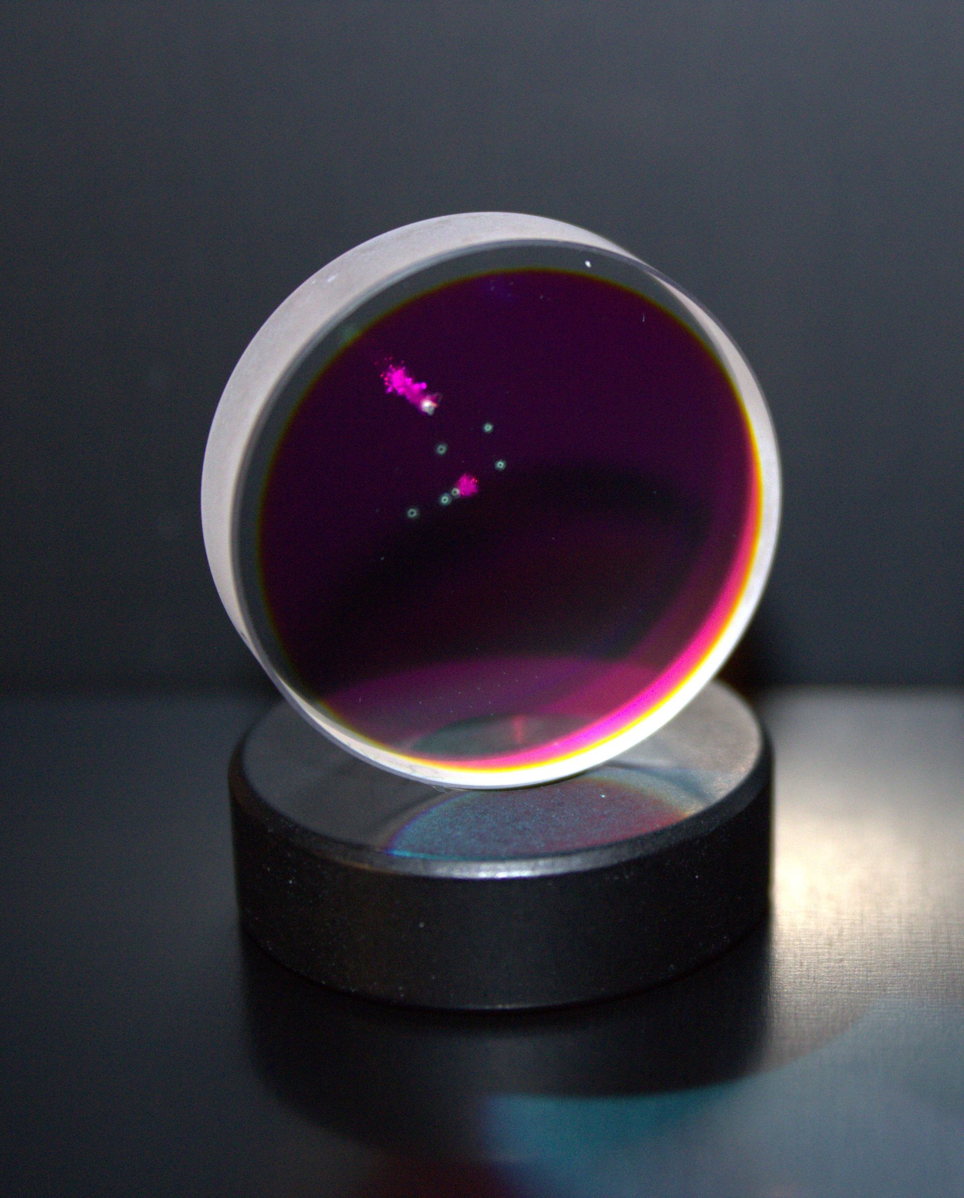
(C) Fraunhofer IOSB
Illustration of the changes

(c) Fraunhofer IOSB / OPOS
LIDT test
LIDT stands for Laser Induced Damage Threshold, characterizing the resilience of optical components to laser radiation. This is a crucial parameter, as no optical component should be damaged by laser radiation, especially when using high-powered laser systems. For example, a surgeon's laser scalpel must not become blunt during a surgery or even cut in an unpredictable direction.
Conducting a LIDT examination
An objective test of resilience to laser radiation is an extremely challenging task, as it depends on a multitude of factors, not least the laser wavelength, pulse duration, etc. Therefore, several methods have been developed and a standard (DIN-ISO 21524) has been established, which is currently being further developed. In all methods, defects are created on the test specimens by laser irradiation with varying energies. In every case, a detector is required that stops further irradiation if damage occurs.
Typically, several defects are induced on the same test specimen at varying irradiance levels (see image on the left). A statistical analysis is then used to determine the stress limit up to which a specific type of optic, coating, etc., can be safely used.
Requirements for a detector of a LIDT testing system
1. Speed: the material treatment is carried out with laser pulses (duration a few µs, pulse rates up to 1 kHz)
2. Automation: Termination signal after an observable material change (before the next pulse)
3. Requirement 1: precise characterization of the optical properties of the sample (at any given time)
4. Request 2: Information about processes during radiation therapy
5. Wish 3: Minimal adjustment effort (especially when testing non-planar optics)
Meeting these requirements and wishes - the realized sensor (TRL 6)
1. Measurements and speed
Individual measurements are performed at a sampling rate of >12 MHz. In this application, four different polarization measurements are performed alternately, uniquely characterizing the polarization state of the detected radiation. These measurements are evaluated directly in the sensor for the individual regions and/or provided as pixels of a 4-channel polarization image at a GigE image interface. One image line is acquired per laser pulse. The acquisition can be configured via a corresponding trigger signal so that polarization information is collected in each image line before, during, and after irradiation (see images on the right).
2. Termination of irradiation
Immediately after the measured values are temporarily stored, they can be evaluated directly within the sensor. Upon detection of a significant change in the polarization values, the sensor sends a signal directly to the test system. The stored values are then displayed as an image line. To aid in setup, the evaluation range limits can be overlaid on the images (see right image).
3. Detailed characterization of the specimen
Knowing the angle of incidence of the laser radiation on a planar test object allows for an ellipsometric evaluation of the polarization measurements, from which, for example, the material properties of the object, the coating, or the layer thickness of a coating can be determined.
The retroreflection ellipsometry principle used eliminates the need for complex detector readjustment for each point examined on a non-planar sample. By additionally modulating the illumination, the rotation angle of the surface normal at the examined object point relative to the detector's coordinate system can be determined for these samples. Knowing the basic shape of the surface thus enables quantitative ellipsometric analysis even on non-planar surfaces.
4. Information about processes during irradiation
See changes during irradiation (from time 0 µs) in the images above right.
5. Adjustment effort
Due to the principle of retroreflection ellipsometry, the sensor only needs to be adjusted once so that the point of impact of its illumination beam on the sample coincides with that of the irradiating laser. Additionally, it is only necessary to visually verify that the reflected beam hits the retroreflector. Readjustment at each individual measurement point of a non-planar test specimen is not required.
Send us a description of your requirements and, if applicable, significant samples for initial non-binding tests, or let us convince you with a device demonstration in your house!
We would be glad to adapt our sensors to your needs or develop new functionality for your application.
Patents
- M. Hartrumpf, "Device and method for the optical characterization of materials": EP11760701.0
- M. Hartrumpf, "Apparatus and method for optically characterizing materials": US9222879B2
- M. Hartrumpf, C. Negara, Configurable Retro-Reflective Sensor System for the Improved Characterization of the Properties of a Sample";US 2019/0170636 A1
Patent Applications
- M. Hartrumpf, C. Negara,
Configurable Retro-Reflective Sensor System for the Improved Characterization of the Properties of a Sample";EP 3 465 145